Tuesday, December 14, 2010
Log 12/14/2010
Today I am finishing up my more detailed 3D CAD drawing and working on my press release, which is due December 21st.
Thursday, December 9, 2010
Log 12/9/2010
I have finished my amended 3D CAD drawing and I'm not really sure of where to go from here, so now I am working on making my drawing more detailed. Right now I've hit a road block while drawing a detailed version of my camera because the dimensions given on the website where I purchased the camera do not seem to match up with the picture of the camera (one side seems entirely too long). Now I am just waiting for my camera to arrive, which should be any day now, so that I can finish my drawing.
Tuesday, December 7, 2010
Amended Orthographic AutoCAD Drawings
*all measurements are in inches
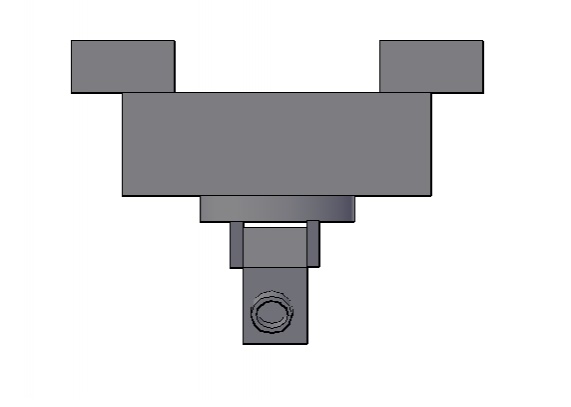
These are the amended orthographic drawings of my project. Please note the change in dimensions of the support beam and control housing box. I also showed that the box is hollow. I also added industrial strength Velcro to the underside of the support beams. My partner, ES, and I came up with this solution after our instructor, DA, suggested that we make my piece removable from the vessel. The edges of the vessel will have industrial strength Velcro so that the two separate pieces will attach and unattach easily.
All drawings done by MM using AutoCAD.
These are the amended orthographic drawings of my project. Please note the change in dimensions of the support beam and control housing box. I also showed that the box is hollow. I also added industrial strength Velcro to the underside of the support beams. My partner, ES, and I came up with this solution after our instructor, DA, suggested that we make my piece removable from the vessel. The edges of the vessel will have industrial strength Velcro so that the two separate pieces will attach and unattach easily.
 |
| Fig. 1: Top View |
 |
| Fig. 2: Bottom view |
 |
| Fig. 3: Front View |
 |
| Fig. 4: Side view |
All drawings done by MM using AutoCAD.
Log 12/7/2010
My partner, ES, and I decided to use plastic industrial strength Velcro to attach our two parts together. The Velcro is strong enough to keep my design attached to the rest of the vessel, but if for whatever reason we need to fix any part of my design we can detach the two parts.
Today I finished my amended orthographic CAD drawings. These include dimension adjustments and the addition of Velcro.
Sources:
Figure 1: http://www.canadiandriver.com/forum/index.php?topic=62241.0
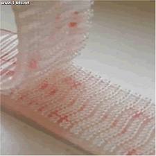 | |||||
| Fig. 1: Plastic industrial strength Velcro made by 3M |
Sources:
Figure 1: http://www.canadiandriver.com/forum/index.php?topic=62241.0
Friday, December 3, 2010
Log 12/3/2010
Last night I ordered the camera, which should arrive in 3-5 business days. I took apart the RC car last night as well. I have pictures that I will upload once I have labels on the pictures explaining what it showing.
Today in class I updated my 3D AutoCAD drawing so that the box holding the electronics was bigger and hollow and the support beams were made longer so that they can fit with the new, larger dimensions of the vessel. I have to add more lights and adjust the materials rendered onto the drawing before I can post it.
Also today, with the help of my classmates, I tested the range of the RC car, which will tell me how far out we can send the vessel. Unfortunately, the RC car only made it about 150 feet and only went another 20 feet when we held the radio control up above our heads. Even with the extra 20 feet, the range of the RC car was 280 feet less than the range of the camera. This means the farthest the vessel can go is about 150 feet because any farther than that we will lose control of it. I had my classmates TH, SW, and CM control the RC car to prove that my camera controller will be easy to operate without extensive training, which makes it very user-friendly.
Wednesday, December 1, 2010
Log 12/1/2010
I have to go through my blog and change any place it says that I will be using a servo because the RC car I will be taking parts from operates both systems on motors. I will make corrections accordingly.
Monday, November 29, 2010
Log 11/29/2010
I will be using the motors, transmitter, and radio control from the RC car I purchased for my project.
Picture Source:
Figure 1: http://www.mailorderexpress.com/shop/prdpics/301469.jpg
 |
| Fig. 1: The RC car I will be taking apart for my project |
Picture Source:
Figure 1: http://www.mailorderexpress.com/shop/prdpics/301469.jpg
Wednesday, November 24, 2010
3D Wireframe Drawings
These are the 3D wire-frame drawings of my solution.
All drawings done by MM using AutoCAD.
 |
| Fig. 1: Side view |
 |
| Fig. 2: Bottom View |
 |
| Fig. 3: Front view |
 |
| Fig. 4: Isometric view |
All drawings done by MM using AutoCAD.
Friday, November 19, 2010
Log 11/19/2010
Though I will not be using a power screwdriver to control my system, this video can give a good visual for how it will work. The circuit board that is used would represent the camera in my system. The camera will tilt similarly by a servo and both of those will sit on top of a rotating motor that will rotate them much like the bottom screwdriver in this video.
Source:
http://www.youtube.com/watch?v=ZerlMpwaguY
Source:
http://www.youtube.com/watch?v=ZerlMpwaguY
Tuesday, November 16, 2010
Log 11/16/2010
Another way to understand how radio controls work and to receive ideas for my system I bought an RC car. It has two controls on its radio controller. One controls turning and one controls whether the car goes forward or backward. Seeing as my final solution will be operated on two systems I decided I can use a similar controller, or the same controller. The RC car moves faster that I would want my project to move so if I were to use the moving parts from the car I would have to gear them down significantly.
Monday, November 15, 2010
Log 11/15/2010 3
And now when I select the "insert image" button the following message comes up:
The feature you requested is currently unavailable. Please try again later.
I don't really have the time to try again later because I need to get the drawings I've had done for weeks onto my blog.
Log 11/15/2010 2
I came home in hopes of uploading all of my drawings again, but a box keeps popping up saying "server rejected," and I'm not really sure what that means so I'll have to ask BH or JC for help again.
3D Rendered Drawing
In this drawing you can see an isometric version of my design. You can see the different materials the parts are made of such as wood for most of the structure, metal for the moving parts, and plastic for the camera.
 |
| Fig. 1: 3D CAD Rendering |
Picture drawn by MM using AutoCAD.
Friday, November 12, 2010
3D AutoCAD Drawings
*Please note that I will be using a motor for both moving parts due to availability rather than a motor and a servo. Also, my partner ES has changed the dimensions of the vessel so some of my measurements may be incorrect, I will make changes accordingly.  | |
| Fig. 1: Bottom View |
This is a 3D AutoCAD drawing of my final solution. This is the bottom view. In this view you can see the camera in the center of the drawing. On either side of the camera are what will be metal support system that will connect to a servo and a rod that will connect to the camera. The servo will cause the rod, which will go across the space between the support structures like a car axle, to rotate 180 degrees. Because the camera will be attached to that rotating rod, the camera will move 180 degrees. The circle that the support structures are attached to is a rotating piece that will be attached to a motor. This will allow the camera and support structure to rotate 360 degrees. All of these parts will be attached to what, in this view, appears to be a large square. This square will be a hollow wooden box that will house the electronics of the system such as the motor, servo, radio transmitter, and battery. The box will be attached to two wooden support beams that will suspend the entire system between the sides of the vessel.
 |
| Fig. 2: Front View |
 |
| Fig. 3: Side View |
 |
| Fig. 4: Side View |
These are the side views of the final solution. You can see the support beams, box, rotating piece, metal support structure, and camera.
 |
| Fig. 5: Top View |
This is the top view of my final solution. Here you can see the top of the hollow wooden box that will house the electronics previously mentioned. You can also see the support beams that will suspend the system between the walls of the vessel.
 |
| Fig. 6: Isometric View |
This is an isometric view of my final solution. Here you can see all of the parts of the system.
All drawings done by MM using AutoCAD.
Thursday, November 11, 2010
Log 11/11/10
Having some problems with uploading and arranging pictures on my blog.
Places that should have visuals or additional visuals:
Also, I'm still working on my 3D CAD drawing. . .
Places that should have visuals or additional visuals:
- Model
- Alternate Solution # 1
- Alternate Solution # 2
- Developmental Work
- Rationale Report
Also, I'm still working on my 3D CAD drawing. . .
Monday, November 8, 2010
Log 11/8/2010
I just handed in my mentor contacts and now I am going through my calendar to make sure it has everything. My model was damaged in transit so I will have to make a new one or fix the old one before my presentation on Wednesday. Currently I am reteaching myself 3D AutoCAD so that I can put a nice 3D drawing in my developmental work.
Friday, November 5, 2010
Orthographic CAD Drawings
*All measurements are in inches
*Please note that I will be using a motor for both moving parts due to availability rather than a motor and a servo. Also, my partner ES has changed the dimensions of the vessel so some of my measurements may be incorrect, I will make changes accordingly.
 |
| Fig. 1: Top view |
 |
| Fig. 2: Bottom View |
 |
| Fig. 3: Front View |
 |
| Fig. 4: Side View |
All drawings done by MM using AutoCAD.
Tuesday, November 2, 2010
Idea Matrix
Criteria | Description |  |  Solution #2 |
Ease of use | Is the product operator friendly? | + | + |
Aesthetic appeal | Is the product aesthetically pleasing? | S | S |
Manufacturability | Is the product easy to manufacture? | - | + |
Low weight | Is the product lightweight and able to fit into the vessel? | - | + |
Energy efficiency | Is the product using the energy efficiently? | S | S |
Safety | Is the product safe to use in the marine environment? Is it safe to handle? | - | + |
S+ | Total positivities | 1 | 4 |
S- | Total negativities | 3 | 0 |
SS | Total ties | 2 | 2 |
Net Score | Total score | -2 | 4 |
Rank | Rank in order of net score (greatest to least) | 2 | 1 |
Continue or combine? | Would you like to continue the design or combine designs? | no | continue |
Fig. 1: Idea matrix
All drawings done by MM.
All drawings done by MM.
Sunday, October 31, 2010
Alternate Solution # 2
*Please note that I will be using a motor for both moving parts due to availability rather than a motor and a servo. Also, my partner ES has changed the dimensions of the vessel so some of my measurements may be incorrect, I will make changes accordingly.
Solution # 2
Solution two has a flat bottom made of Plexiglas. The camera will be suspended from the top of the vessel looking down onto the glass bottom. The camera will move on two different systems to film through the Plexiglas.
The main structure that will attach the camera and mechanisms to the vessel will be made of wood, much like the vessel. The mechanism that will move the camera will be made of metal. The wood can be found in the Systems lab, but the mechanical pieces will be more specialty items that will have to be ordered online, along with the camera.
The camera will be operated on two systems; a rotating motor and a servo that will pivot the camera 180 degrees. The camera, the camera's radio transmitter, and the part the servo will connect to and controll will be attached to the rotating motor. Both systems will be radio controlled from the shore. The camera will transmit the film to a TV, computer, or camcorder wirelessly.
If the bottom of the vessel is flat and made of Plexiglas it would be less fragile than the dome and easier to replace or fix than the dome as well. Because the systems will allow the camera to spin 360 degrees in the z plane and pivot 180 degrees in the x-y plane the camera will be able to view the entire bottom of the vessel.
Having two systems will make operating the camera less user friendly, but should not be too difficult. The camera will not be able to film anything other than what is below the camera, unlike in solution two. This will limit the view of the camera.
All drawings done by MM.
Solution # 2
Solution two has a flat bottom made of Plexiglas. The camera will be suspended from the top of the vessel looking down onto the glass bottom. The camera will move on two different systems to film through the Plexiglas.
The main structure that will attach the camera and mechanisms to the vessel will be made of wood, much like the vessel. The mechanism that will move the camera will be made of metal. The wood can be found in the Systems lab, but the mechanical pieces will be more specialty items that will have to be ordered online, along with the camera.
The camera will be operated on two systems; a rotating motor and a servo that will pivot the camera 180 degrees. The camera, the camera's radio transmitter, and the part the servo will connect to and controll will be attached to the rotating motor. Both systems will be radio controlled from the shore. The camera will transmit the film to a TV, computer, or camcorder wirelessly.
If the bottom of the vessel is flat and made of Plexiglas it would be less fragile than the dome and easier to replace or fix than the dome as well. Because the systems will allow the camera to spin 360 degrees in the z plane and pivot 180 degrees in the x-y plane the camera will be able to view the entire bottom of the vessel.
Having two systems will make operating the camera less user friendly, but should not be too difficult. The camera will not be able to film anything other than what is below the camera, unlike in solution two. This will limit the view of the camera.
 |
| Fig. 1: Front view |
 |
| Fig. 2: Side view |
 | |||
| Fig. 3: Top View *All dashed lines are hidden lines | |
Friday, October 22, 2010
Log 10/22/2010
I am redrawing my alternate solutions, so that the drawings are more on par with my partner, ES's, vessel design. I have a better idea of what kind of cameras I need to be looking for, but I am still having trouble finding the moving parts I need. I may need to get a PTZ (pan/tilt/zoom) camera and just concern myself with building something to hold it.
Wednesday, October 20, 2010
Alternate Solution # 1
Solution one has a glass dome centered on the bottom of the vessel that will be designed by my partner ES. The camera and camera system will sit in the vessel so that the camera is in the center of the glass dome. The dome will be clear so that the camera can film through it.
The part that will hold the camera will be mostly constructed of wood, much like the rest of the vessel. The actual attachment for the camera will be a ball and socket joint that will be made of metal. This kind of joint would allow the camera to move in many different directions. The glass dome will be blown glass that can be found at glass stores, such as Hot Sand in Asbury Park, NJ. The glass has to be absolutely clear so that the film is not distorted. The dome will be sealed to the wooden hull to prevent water from getting in. The camera and camera system will be wireless and radio controlled from the shore.
The camera will be moved on a single system. A ball and socket joint moves on several planes and allows the camera to view the benthic organisms at many different angles. This joint will be radio operated allowing the operators to be able to have few limitations while filming.
This solution is good because it allows the camera to be in the middle of the action, so to speak. The camera can film fish swimming directly next to it, not just beneath it. Also, if the fish swims around the vessel the camera can follow it. It can still film below the vessel, but it will not be limited to that.
Solution one will be fragile because the glass dome will protrude from the bottom of the vessel. There is also a possibility that the dome will create a fish-eye effect and distort the film. The glass dome would also be heavy, which may make the vessel sit low in the water.
 |
| Fig. 1: Front view |
 |
| Fig. 2: Side View |
 |
| Fig. 3: Top View |
*all dashed lines are hidden lines
All drawings done by MM.
All drawings done by MM.
Monday, October 18, 2010
Limitations
*all limits only apply to my portion of the project*
The limitations of the project are the boundaries that the project must work inside of in terms of cost and construction.
- Camera and attachment must cost under $200
- Weight of camera and attachment must not exceed rate of buoyancy
- Camera and attachment must not exceed the size of vessel
- Vessel must stay within 450 feet of radio control so that it is within range of the transmitter
Saturday, October 16, 2010
Background Information
 |
| Fig. 2: Barnegat Bay frozen over |
 |
| Fig. 1: Sandy Hook Bay Frozen over |
It is winter time in Sandy Hook,
My team's ROV is designed to help out in this situation. Scientists want to preserve marine habitats, but they still need to be able to conduct research. With an ROV there would be far less disruption than if a person were to collect information themselves. Scientist are not the only people who would benefit from our ROV. Scuba divers who film underwater for work or pleasure are limited to warm weather seasons in places like New Jersey where the weather can be cold and unpleasant from fall to early spring.
 |
| Fig. 3: Ice on a bay |
 |
| Fig. 4: Scuba diver filming marine life |
 |
| Fig. 5: Remote controlled toy boat |
 |
| Fig. 6: Clear canoe |
 | ||
| Fig. 7: Tourists observe marine life on glass bottom tour boat. |
Sources:
- Figure 1: http://www.windsurfresource.com/sandy_hook.htm
- Figure 2: https://blogger.googleusercontent.com/img/b/R29vZ2xl/AVvXsEgkqTOltULlPoRMJx8DElEc0tmLBPRifpoIBygTcaHu5y9O_MADBRBdxWgto2giv7wteyUSMwrHkLUw9_LTLdMAvGXSLQp7v-N-GyYctfdT0NpDQCpLLlGzY-WXaikBgvxglXLMEdrF5iU/s320/IMG_2622.JPG
- Figure 3: http://www.ventureout.org/image/bay.jpg
- Figure 4: http://picsdigger.com/image/379a7f46/
- Figure 5: http://images.hobbytron.com/XT-757059-lg.jpg
- Figure 6: http://www.opulentitems.com/assets/images/KayakMolokini1diff.jpg
- Figure 7: http://www.elitetoursfl.com/images/glass-bottom-boat-picture.jpg
Log 10/16/2010
Fixed specs and limits and finally posted research. The research is not summer research because my summer research was unrelated to what the project entails now.
Wednesday, October 6, 2010
Tuesday, October 5, 2010
Log 10/5/2010
Just learned a way to get around the picture uploading problems; now I can put up more of my posts.
Friday, October 1, 2010
Log 10/1/2010
Yesterday, I continued my search for a mentor who knows about underwater filming. I have two potential mentors and if they can't help me they know plenty of people who can.
Thursday, September 30, 2010
Plan of Procedures
Supplies:
- Camera, transmitter, and attachments
- Motor for tilting camera
- Rotating Motor
- Wood from Systems lab
- Wood
- Wires
- Metal hinge
- Screw driver
- Drill
- Saws
- Sandpaper
- Glue
- Vice
- Support structure that will attach to vessel
- Motor, servo, and battery housing box
- Rotating motor
- Servo operated pivot
- Camera
- Battery
- Wires connecting moving parts and camera to battery
- Cut wood to dimensions of support structure and housing box
- Glue pieces together
- Place motor, servo, and battery in housing box with wires connecting them to their moving parts
- Motor will connect to the rotating piece
- Servo will connect to the pivoting piece
- Attach camera and transmitter to pivoting piece
- Attach motor, servo, and camera to battery and transmitter
- When building is complete go through testing procedure
Formal Progress Update Presentation
* Design Brief
- Team
- To design and construct a remote controlled model vessel that marine biologists will use to film marine life in bay type situations in a variety of cold and/or severe weather conditions
- Individual
- To design, model, and construct a flexible camera attachment that is remote controlled
- Team
- To design and construct a remote controlled model vessel that marine biologists will use to film marine life in bay type situations in a variety of cold and/or severe weather conditions
- Individual
- To design, model, and construct a flexible camera attachment that is remote controlled
* Research and Background Information
- Cold weather is not good for research
- Need for a research vessel that won't disrupt habitat
- Looked into ROVs with cameras
- Looked at online hobby shops for cameras and batteries
- Cold weather is not good for research
- Need for a research vessel that won't disrupt habitat
- Looked into ROVs with cameras
- Looked at online hobby shops for cameras and batteries
* Specifications and Limitations
- Specifications
- Camera will film marine organisms that are mostly stationary in the colder months.
- Camera will be attached to a moving apparatus that will sit inside the vessel.
- Camera and attachment will be remote controlled from the shore.
- Camera will be live feed so that operators can see what they are filming.
- Camera attachment will allow camera to move 360 degrees
- Limitations
- Camera and attachment must be cost effective; under $200
- Weight of camera and attachment must not exceed rate of buoyancy
- Camera and attachment must not exceed the size of vessel
- Camera attachment must be constructed using tools from the Systems lab
- Camera attachment must be constructed from easily accessible materials or materials provided in the Systems lab
* Testing Procedures
1. Check that camera is filming and working properly by connecting the live feed transmitter to a screen and observing whether or not the view is clear.
2. If view is unclear, clear it. Lens of camera may need to be cleaned if view on screen is blurred.
3. Make sure nothing is in the way of moving parts by moving all parts using the radio control and ensuring that nothing limits movement that shouldn't.
4. Check to see if rotating motor rotates 360 degrees by using the radio control.
5. Examine glass to ensure that it is clean and clear without any cracks or damage that could obstruct the camera's view or be a danger to the vessel or system.
6. Check to see if servo pivots the camera properly using the radio control.
7. When filming is complete run through film and make sure nothing went wrong while filming.
-Questions to ask:
- If the view of the camera is obstructed or blurred, what is causing that? Can it be fixed or prevented?
- If something doesn't move when or how it should, why doesn't it?
- If something is limiting the movement of a part of the system can it be fixed or prevented?
- If something went wrong during filming, what was it and can it be fixed or prevented?
- Did all of the tests work? Did the system malfunction despite the tests?
* Brainstorming and Alternate Solutions
- Brainstorming
- Rough drawings of preliminary ideas and brainstorming
- Alternate Solutions
- Alternate Solution #1
- Alternate Solution #2
- Brainstorming
- Rough drawings of preliminary ideas and brainstorming
- Alternate Solutions
- Alternate Solution #1
- Alternate Solution #2
* Rationale Report
- Rationale
- Alternate Solution #1
- Useful
- Usable
- Desirable
- Producible
- Profitable
- Differentiated
- Alternate Solution #2
- Useful
- Usable
- Desirable
- Producible
- Profitable
- Differentiated
- Idea matrix
- Alternate Solution #1
- Alternate Solution #2
- Rationale
- Alternate Solution #1
- Useful
- Usable
- Desirable
- Producible
- Profitable
- Differentiated
- Alternate Solution #2
- Useful
- Usable
- Desirable
- Producible
- Profitable
- Differentiated
- Idea matrix
- Alternate Solution #1
- Alternate Solution #2
* Developmental Work
- Orthographic CAD drawings
- 3D CAD drawings
- 3D rendered CAD drawing
- Plan of procedures
- Orthographic CAD drawings
- 3D CAD drawings
- 3D rendered CAD drawing
- Plan of procedures
Model
This model is 1/2 the actual size of the project.
All pictures taken by MM.
 |
| Fig. 1: Bottom view of model Orange piece models camera and moving parts |
 |
| Fig. 2: Side and bottom view of model Orange piece models camera and moving parts |
 |
| Fig. 3: Top view of model Orange pieces modeling motors, batteries, and circuit board |
 |
| Fig. 4: Side view of model suspended similar to how it will be in the vessel Orange piece models the camera and moving parts |
All pictures taken by MM.
Mentor Contacts
Mentor Name: DH
*Writing in plain text are my E-mails and writing in italics are the mentor’s e-mails
*All mentor contacts are E-mails
Date: October 16th
Question:
Dear DH,
Thank you so much for offering to be my mentor, I really appreciate it. My blog is a bit of a mess at the moment, but once it's all up to date I would like to send you a link so that you can see what my project is about.
Thanks again!
Sincerely,
MM
Response:
Not a problem. Let me know what information you need from me for your Mentor forms or whatever.
I tend to check my email in the evenings, so if you send me email in the morning I will generally see it by 9-10PM. If you need me before that ... send a text message to ***-***-****
Date: October 21st
Question:
Dear DH,
Here is a link to my blog so that you can see what I have done so far: se2glassbottomboatmm.blogspot.com At this time I am considering attaching the camera to a remote controlled ball and socket joint so that the camera can move in all directions. I have been having trouble finding anything like that, so I was wondering if you either knew of such a product or knew of a good alternative. I really don't know anything about mechanics or electronic things, so I could really use some advice.
Thanks,
MM
Response:
MM,
Will this be a video or still picture camera? If you put it on a gimbal mount (ball), how will you know which way it is pointing? Will you have to send the remote image back to the shore so you can tell what you are looking at?
You can buy a PTZ camera from multiple sources, not cheap, some deals on Ebay, but prices tend to be at a premium. PTZ stands for (Pan, Tilt, Zoom). Google "PTZ camera," to check this out. Many are remote controlled via a PC. To be remote controlled from shore ... a bit more complicated, so back to the question above.
Your requirements say the camera must move through 360 degrees. In what plane (or planes)? Very few retail PTZ cameras can do that (most can only do about 250 degrees rotation and maybe 50 degrees tilt.
If you think you need to build your own camera attachment, read up on "stepper" motors and stepper motor controls. Not easy stuff. You could "cobble" something together using simple geared down motors and some R/C controls. See
http://www.youtube.com/watch?v=ZerlMpwaguY
What is your required field of view? What angles? Distance? Focus? Autofocus may not work through plastic or glass (water will appear to be a flat surface to the camera).
Hope you like both electronics and mechanics.
DH
Date: October 22nd
Question:
DH,
The camera will be a video camera because we planned to have a live feed so that we would know what we were filming. Also, the camera will be mounted above the flat glass bottom and it needs to be able to move around so that it can film the entire bottom of the vessel. We do not want the camera to be limited to filming only what is directly below it. A PTZ camera seems to be what I need, but the controls and price could be a problem.
Thanks again,
MM
Response:
MM,
You need to broadcast video to the shore ? In real time ?
When you say "bottom of the boat," do you really mean "the bottom of the boat?" If the camera sits above the glass bottom, how can it see the bottom of the boat?
Or, do you mean it sits down in a glass bubble under the boat above the glass bottom (ie: the glass bottom also has glass sides.
So then say the camera is sitting below the boat in the glass bottom (ball, whatever), what angle up and down does it need to see? Does it really need to see the paint on the bottom of the boat? ;-)
DH
Date: October 22nd
Question:
DH,
I found this PTZ camera on ebay. It's really cheap now but there's a little over a week left to bidding so I doubt it will stay that way. I don't really understand all the tech lingo, but it says that the camera does not need to be hooked up to a computer. We need a tether for the vessel anyway, so any wires we may end up with can be attached to the tether.
Thanks,
MM
Response:
MM,
Oh ... I thought you guys were doing radio remote control. I thought I read that in one of the blogs. Tethering makes life easier, but messy (dragging wires around in the water).
There was nothing attached to the message that I could look at. Did you send me the link to the camera ?
DH
Date: October 24th
Question:
DH,
I think originally we were going to, but the vessel needed a tether so if I can't find a wireless camera it would not be a big deal. Sorry I didn't realize I didn't include the link and now I can't find that camera, so I guess I'll just have to keep looking.
-MM
Response:
Your tether may make steering a small boat impossible. It would sink in the water and act like an anchor ... or a brake. What's the tether for?
Date: October 25th
Question:
DH,
We need a tether so we don't accidentally go out of range and then have to go retrieve the vessel because the point was to avoid disrupting the area.
I found this camera, which is good for how small the boat will be, but I think it has a wire
-MM
Response:
Nice technology. Very small and light. Price seems low. Does it really include all the receiver pieces as well?
From what I read, no, you will not need a wire (tether) to receive the video. It will broadcast some 300-400 feet to your receiver setup. Over water ? Might need to test it to be sure.
Not sure how it will focus ... that didn't seem obvious in the specs. Must be fixed focus.
You will need to design your movable camera mount as it has no positioning controls.
Tether ... a safety tether ... sure, like pulling a floating single fishing line behind it or something so you can retrieve it, but for electronic controls ??... can't see how the line won't cause you grief trying to drag it in the water. Pick your favorite wire ... get 100 feet of it, multiply by 5 or 6 conductors to control this or that ... now drag it through the water ... :-\
Date: October 26th
Question:
DH,
If the camera is radio controlled and the vessel is radio controlled then maybe all we'll need is a fishing line to keep it in range?
-MM
Response:
My thinking exactly. If you need a fail-safe, keep it simple. Haul it back with a fishing rod.
Subscribe to:
Comments (Atom)