*Please note that I will be using a motor for both moving parts due to availability rather than a motor and a servo. Also, my partner ES has changed the dimensions of the vessel so some of my measurements may be incorrect, I will make changes accordingly.  | |
| Fig. 1: Bottom View |
This is a 3D AutoCAD drawing of my final solution. This is the bottom view. In this view you can see the camera in the center of the drawing. On either side of the camera are what will be metal support system that will connect to a servo and a rod that will connect to the camera. The servo will cause the rod, which will go across the space between the support structures like a car axle, to rotate 180 degrees. Because the camera will be attached to that rotating rod, the camera will move 180 degrees. The circle that the support structures are attached to is a rotating piece that will be attached to a motor. This will allow the camera and support structure to rotate 360 degrees. All of these parts will be attached to what, in this view, appears to be a large square. This square will be a hollow wooden box that will house the electronics of the system such as the motor, servo, radio transmitter, and battery. The box will be attached to two wooden support beams that will suspend the entire system between the sides of the vessel.
 |
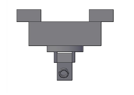
| Fig. 2: Front View |
 |
| Fig. 3: Side View |
 |
| Fig. 4: Side View |
These are the side views of the final solution. You can see the support beams, box, rotating piece, metal support structure, and camera.
 |
| Fig. 5: Top View |
This is the top view of my final solution. Here you can see the top of the hollow wooden box that will house the electronics previously mentioned. You can also see the support beams that will suspend the system between the walls of the vessel.
 |
| Fig. 6: Isometric View |
This is an isometric view of my final solution. Here you can see all of the parts of the system.
All drawings done by MM using AutoCAD.
MM,
ReplyDeleteGood rendering!
Where is the electrical considerations? Also how is this attached to the vessel.
DA
MM
ReplyDeletePlease add leaders and notes to drawings.
Note I am very concerned as to the small size of this boat (6" X 12"). Meeting needed to consider larger size or why this size is necessary. In addition the placement of your camera and its support pieces must be perfectly centered to prevent tipping!!
DA