
Sunday, May 1, 2011
Thursday, March 31, 2011
Final Product
 |
| Fig. 1: Front view of final constructed product |
 |
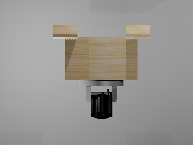
| Fig. 2: Top view of final constructed product, here you can see the receiver/battery box in the top left corner and the gears and the motor in the bottom left corner |
 |
| Fig. 3: Isometric view of final constructed product |
All pictures were taken by MM.
Testing
My partner, ES, and I did preliminary testing. I tested my part in a safe and dry environment to show that the system worked in perfect conditions. My partner then took the vessel and camera attachment home to test them together and the vessel was able to move with the attachment included. Below are some pictures of what I did to test that the camera and controller worked.
All pictures taken by MM.
 |
| Fig. 1: Student, MR, films clay fish in computer lab with camera |
 |
| Fig. 2: Everything the camera films appears on the TV live because the camera's receiver is hooked up to the TV |
All pictures taken by MM.
Wednesday, March 30, 2011
Finalized AutoCAD Drawings
 |
| Figure 1: Side view of final design |
 |
| Figure 2: Front view of final design |
 |
| Figure 3: Front rendered view of final design |
All drawings were done by MM using AutoCAD.
Wednesday, March 23, 2011
Gear Configuration
 |
| Fig. 1: Rudimentary drawing of the way the gears will be configured in the box |
Drawing done by MM using Microsoft Paint.
Thursday, March 17, 2011
Log 3/17/2011
Last night I worked for three hours with my mentor supervising me. I finished painting the entire wooden structure. I then covered the paint with clear acrylic sealant. I epoxied the support beams of the structure to the box and screwed the receiver/battery piece to the box. To give the beams more support I epoxied and screwed corner braces between the box and the support beams. I also epoxied on one side of the plastic Velcro that will attach my piece to my partner ES's piece. I just did some touch ups to the paint on my structure then all I will have to do is screw the camera on and test. I will use the rest of the period to work on my poster.
Wednesday, March 16, 2011
Log 3/16/2011
Today I started painting my structure. Tonight I will re-assemble it and attach the velcro and I will be done. All I have left to do is finish my poster and other work.
Tuesday, March 15, 2011
Log 3/15/2011
Today in class I finally finished assembling the first system in my project and it didn't work. The gear shafts weren't straight enough. Tonight I took the project home and worked for 3 hours taking it apart for the third time and trying to find yet another solution. While trying to hammer a nail in I cracked the box. While trying to move other pieces around the wires on the receiver tore and I had to solder them again. I had to cut and re-cut, drill and re-drill and the gears were still giving me trouble. I can't honestly see this project getting done the way I originally planned.
There were some things I could not determine without having the product actually assembled and one of those things was the power of the first motor. Once I assembled everything I realized that it was not strong enough to turn a second motor, the camera, and more gears. Because of this and the time limit that is fast approaching I have decided to amend my design so that the camera will only turn 360 degrees and not tilt. This will not be a devastating blow to the design seeing as the glass bottom of the boat is so small.
All that is left to do is paint my portion of the project and re-attach the support beams as well as glue on the plastic velcro. Now that I have cut a major part of my work out I should be able to finish on time.
Monday, March 14, 2011
Update to Mr. Alfonse 3/14-18/2011
By the end of this week I hope to have all the inner components in place including the motor and battery pack. I have to drill another hole for the gear shaft. The gears should all be in place by the end of this week and I will be able to start work on the outer components including the camera and tilt mechanism.
Friday, March 11, 2011
Progress 3/11/2011
 |
| Fig. 1: View of half-assembled support box with descriptions of the parts of the box |
 |
| Fig. 2: Second view of half-assembled box |
All pictures taken by MM.
Log 3/11/2011
I left my project at home, so I am spending this class period updating my blog and calendar and typing up my mentor contacts.
Wednesday, March 9, 2011
Log 3/9/2011
Today I measured out where my gears need to be located inside of the box. I drilled a shallow hole in the bottom of my box and put a piece of a a coffee stirer that would act as low friction base for the gear shaft into the hole. I also glued the wooden pieces that will keep the first motor in place as well as the pieces of wood that will hold the receiver and battery pack in place.
Monday, March 7, 2011
Update to Mr. Alfonse 3/7-11/2011
Last week I lost two days of work because I had a class trip on Thursday and went home early on Friday. Today I will finish sanding, hopefully early in the class period. I should have the gears for my 360 rotation in place and working by the end of this week.
Wednesday, March 2, 2011
Update for Mr. Alfonse 2/28- 3/4/2011
Today I will be waiting for wood filler to dry. While it is drying I will measure the gears and motors and determine the distances at which I will have to place the gears. I will hopefully have the gears and mechanisms ready to install by the end of Friday. I will be losing work time tomorrow because of the trip to New York, but hopefully I will still be able to meet my goal at the end of the week.
Friday, February 25, 2011
Log 2/25/2011
Last night I worked with my mentor for two hours and lengthened the wires attached to the motors and attached the wires to connectors. With these connectors I can easily attach and detach my motors to my receiver and battery. This will make building easier because I can move parts around without the wires getting in the way or being too limiting. Today I will glue together my new support structure whose inner dimensions are 4x4.
Update to Mr. Alfonse 2/25/2011
The dimensions of my support structure were too small so I had to re-cut and rebuild my support structure from scratch.
Tuesday, February 22, 2011
Testing Questions
- Are there batteries in the system and radio controller?
YES / NO / OTHER: ________________________________________ - Is the system on?
YES / NO / OTHER: ________________________________________ - Is the camera attached to the power source?
YES / NO / OTHER: ________________________________________ - Is the camera receiver hooked up to a screen/DVR?
YES / NO / OTHER: ________________________________________ - Does the support structure easily and properly attach to the vessel?
YES / NO / OTHER: ________________________________________ - Is the camera transmitting a picture to the screen/DVR?
YES / NO / OTHER: ________________________________________ - Is the picture clear of blockages?
YES / NO / OTHER: ________________________________________ - Is the reception of the picture clear? YES / NO / OTHER: ________________________________________
- Can the picture show what is outside of the glass bottom? YES / NO / OTHER: ________________________________________
- Does the up control rotate the camera 360º clockwise smoothly? YES / NO / OTHER: ________________________________________
- Does the down control rotate the camera 360º clockwise smoothly? YES / NO / OTHER: ________________________________________
- As the camera rotates, does the picture remain clear of blockages?YES / NO / OTHER: ________________________________________
- As the camera rotates, does the reception remain clear?
YES / NO / OTHER: ________________________________________ - As the vessel moves, does the picture remain clear of blockages? YES / NO / OTHER: ________________________________________
- As the vessel moves, does the reception remain clear? YES / NO / OTHER: ________________________________________
- As the vessel moves, is the picture showing what is in the water through the glass bottom?
YES / NO / OTHER: ________________________________________ - As the vessel moves, does the support structure stay in place? YES / NO / OTHER: ________________________________________
- When the vessel’s testing is complete, is the support structure easy to remove from the vessel?
YES / NO / OTHER: ________________________________________
Update to Mr. Alfonse 2/21-25/2011
I'm a little more than halfway done with my project. Most of the work I have to do is assembly because the structural piece is complete. I have to put the gears in place, attach the camera, and finish the wood on the structural part. I bought a gear kit so I have all the materials I need to complete the project and once I get past a certain roadblock I should be able to finish the project within the next couple of weeks.
This roadblock has caused a lot of problems for me and wasted a lot of valuable work time. I cannot find the RPM of the motors I am using so I cannot mathematically calculate a way to gear them down. I hadn't originally planned on doing it mathematically because I do not know what is considered "slow RPM" I was just going to work hands-on until I found the right speed. I was going to solder the wires that tore back to the motors so that I could work with the gears, but it was brought to my attention that I should do the gearing mathematically. I wasted a lot of time trying to find the RPM of the motors and was unable to find out what it was. I intend to go with my original plan to work hands-on with the gearing. I will be at a program up at NJIT from Wednesday night to Friday and unless I get a monumental amount of work completed tonight at home I can't imagine I will make much progress by tomorrow.
This roadblock has caused a lot of problems for me and wasted a lot of valuable work time. I cannot find the RPM of the motors I am using so I cannot mathematically calculate a way to gear them down. I hadn't originally planned on doing it mathematically because I do not know what is considered "slow RPM" I was just going to work hands-on until I found the right speed. I was going to solder the wires that tore back to the motors so that I could work with the gears, but it was brought to my attention that I should do the gearing mathematically. I wasted a lot of time trying to find the RPM of the motors and was unable to find out what it was. I intend to go with my original plan to work hands-on with the gearing. I will be at a program up at NJIT from Wednesday night to Friday and unless I get a monumental amount of work completed tonight at home I can't imagine I will make much progress by tomorrow.
Thursday, February 10, 2011
Log 2/10/2011
Things I have left to do:
Sand off excess glue on structureDrill hole in bottom of boxBuy gears to gear down motorsConfigure gears and lengthen wiresFinish and seal wood componentsAsembleTest using remote controlAttach to ES's boat- Test within boat
Wednesday, February 9, 2011
Log 2/9/2011
I just have to finish sanding off excess glue and then the structural construction will be complete.
Friday, February 4, 2011
Log 2/4/2011
Waiting for glue to dry. The construction of the wooden structure is about 75% done at this point.
Monday, January 31, 2011
1/31/2011
Just finished STEMM report and handed it in. I will try to get it on my blog, but the file might be too big.
Friday, January 28, 2011
Log 1/28/2011
The marking period is over and midterms are almost over too. I have been working on my STEMM report, which is due on my blog next Monday, January 1st.
Tuesday, January 18, 2011
Construction (support structure)
Below are pictures of the construction of my support structure, which is made out of 1/4 in. thick plywood.
*Please note that due to last minute design changes the dimensions of the box pictured in figure 4 were not big enough and a larger box will be made tomorrow.
All pictures taken by MM.
 |
| Fig. 1: A view of the wood before it was cut |
 |
| Fig. 2: A view of the wood after it was cut |
 |
| Fig. 3: Me measuring the wooden box |
 |
| Fig. 4: A view of the wooden pieces glued together to make the box that will hold the electronics |
*Please note that due to last minute design changes the dimensions of the box pictured in figure 4 were not big enough and a larger box will be made tomorrow.
All pictures taken by MM.
Log 1/18/2011
Presentations were pushed back a day so my partner, ES, and I will most likely be presenting on Thursday the 20th.
Today I handed in my presentation outline, which can be found here: http://se2glassbottomboatmm.blogspot.com/2011/01/mp2-presentation-outline.html
Today I handed in my presentation outline, which can be found here: http://se2glassbottomboatmm.blogspot.com/2011/01/mp2-presentation-outline.html
Construction (Electronics)
Below are pictures of the electronics I took out of my RC car.
All pictures taken by MM.
 |
| Fig. 1: A view of the empty battery pack attached to the circuit board, transmitter, and motors |
 |
| Fig. 2: Another view of the battery pack for the motors, transmitter, and circuit board |
 |
| Fig. 3: A view of the electronics for the camera attachment The transmitting wire is the red wire, the circuit board is covered by the plastic cover |
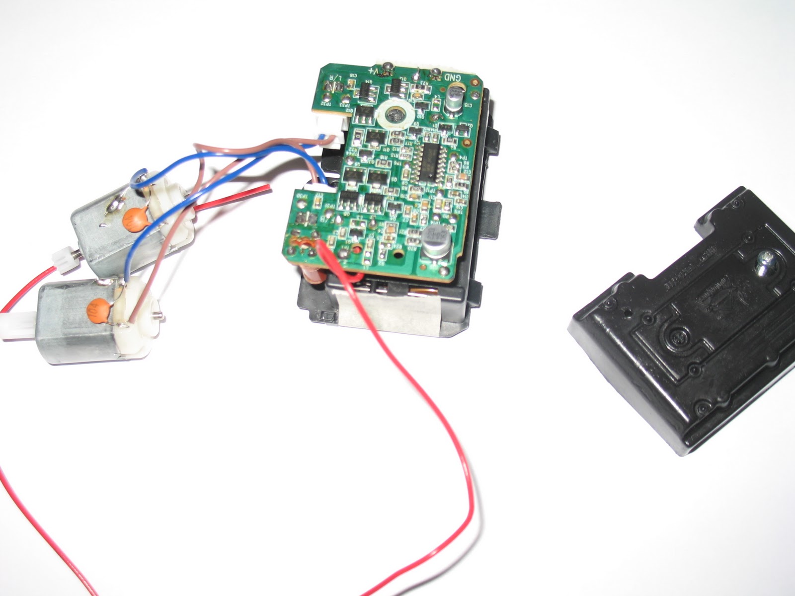 |
| Fig. 4: A view of the exposed circuit board that controls the two motors shown on the left side of the picture and the plastic cover is shown on the right side of the picture |
All pictures taken by MM.
MP2 Presentation Outline
I. Introduction
A. Mae McKenna
B. Senior at MAST
C. Systems Engineering II
A. Mae McKenna
B. Senior at MAST
C. Systems Engineering II
II. Background
A. Scientists can’t enter water in winter months
B. Need to observe marine life year-round
A. Scientists can’t enter water in winter months
B. Need to observe marine life year-round
III. Design Brief
A. Team Design Brief
1. To design and construct a remote controlled model vessel that marine biologists will use to film marine life in bay type situations in a variety of cold and/or severe weather conditions.
B. Individual Design Brief
2. To design, model, and construct a flexible camera attachment that is remote controlled.
IV. Construction Intro
A. Chosen Solution
1. Amended orthographic drawings
B. Model
1. Pictures of model
C. Final Solution
1. 3D CAD drawing
A. Chosen Solution
1. Amended orthographic drawings
B. Model
1. Pictures of model
C. Final Solution
1. 3D CAD drawing
V. Construction Process
A. Construction Progress
1. Pictures of working on project
B. Construction Process
1. Gluing all pieces together because screws would split wood
2. Take motors, battery pack, and transmitter out of the RC car
3. The motors will stick out of the box and attach to gears
A. Construction Progress
1. Pictures of working on project
B. Construction Process
1. Gluing all pieces together because screws would split wood
2. Take motors, battery pack, and transmitter out of the RC car
3. The motors will stick out of the box and attach to gears
VI. Summary
A. Glass Bottom Radio Controlled Research Vessel
B. Work completed
1. Main structure construction
2. Battery pack and transmitter has been detached from RC car
3. About 50% done- 50% left to go
A. Glass Bottom Radio Controlled Research Vessel
B. Work completed
1. Main structure construction
2. Battery pack and transmitter has been detached from RC car
3. About 50% done- 50% left to go
VII. Conclusion
A. That concludes my presentation
B. Any Questions?
A. That concludes my presentation
B. Any Questions?
Thursday, January 13, 2011
Amended 3D Rendered CAD Drawings
Note the change in design. The support beams are now tapered off at the ends so that when we put the water proof tarp over top the beams won't jut out and pull or tear the tarp. Also I have included the plastic Velcro in this drawing and made the box for the controls deeper to fit all the electronics.
All drawings done by MM using AutoCAD.
 |
| Fig. 1: Top Isometric View |
 |
| Fig. 2: Bottom Isometric View |
 |
| Fig. 3: Front view |
All drawings done by MM using AutoCAD.
Tuesday, January 11, 2011
Log 1/11/2011
I was going to continue making my own batery pack as well as taking the circuit board out of the RC car today, but unfortunately I am unable to locate the RC car. This can be a major issue seeing as I need it for all moving parts of my project.
Monday, January 10, 2011
Log 1/10/2011
Just came up with a solution to our waterproofing problem. It seems like it should work though I will check with one of my mentors first.
Friday, January 7, 2011
Log 1/7/2011
My father, RMM, will act as a second mentor for me because he is knowledgeable about motors and robotics. It will be easier to receive help from him because I see him everyday and can have face-to-face contact with him and do hands-on work with him.
Use of RC Car
 |
| Fig. 1: RC car wheels turned to the right |
 |
| Fig. 2: RC car wheels turned to the left |
 |
| Fig. 3: Exposed motors in the RC car |
 |
| Fig. 4: Exposed circuit board of the RC car |
Below (Figure 5) is the battery pack attached to the RC car. Currently the battery pack blocks access to the receiver, so with the help of my other mentor, RMM, I will have to make a whole new battery pack for the receiver and motors.
 |
| Fig. 5: Exposed battery pack on RC car |
All pictures taken by MM.
Subscribe to:
Comments (Atom)