 |
| Fig. 1: The RC car I will be taking apart for my project |
Picture Source:
Figure 1: http://www.mailorderexpress.com/shop/prdpics/301469.jpg
|
| Fig. 1: The RC car I will be taking apart for my project |
 |
| Fig. 1: Side view |
 |
| Fig. 2: Bottom View |
 |
| Fig. 3: Front view |
 |
| Fig. 4: Isometric view |
 |
| Fig. 1: 3D CAD Rendering |
*Please note that I will be using a motor for both moving parts due to availability rather than a motor and a servo. Also, my partner ES has changed the dimensions of the vessel so some of my measurements may be incorrect, I will make changes accordingly.  | |
| Fig. 1: Bottom View |
 |
| Fig. 2: Front View |
 |
| Fig. 3: Side View |
 |
| Fig. 4: Side View |
 |
| Fig. 5: Top View |
 |
| Fig. 6: Isometric View |
 |
| Fig. 1: Top view |
 |
| Fig. 2: Bottom View |
 |
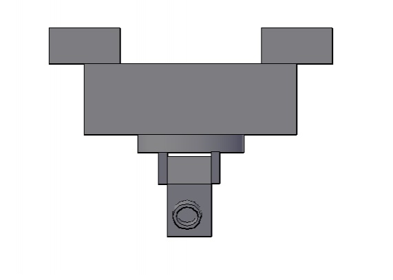
| Fig. 3: Front View |
 |
| Fig. 4: Side View |
Criteria | Description |  |  Solution #2 |
Ease of use | Is the product operator friendly? | + | + |
Aesthetic appeal | Is the product aesthetically pleasing? | S | S |
Manufacturability | Is the product easy to manufacture? | - | + |
Low weight | Is the product lightweight and able to fit into the vessel? | - | + |
Energy efficiency | Is the product using the energy efficiently? | S | S |
Safety | Is the product safe to use in the marine environment? Is it safe to handle? | - | + |
S+ | Total positivities | 1 | 4 |
S- | Total negativities | 3 | 0 |
SS | Total ties | 2 | 2 |
Net Score | Total score | -2 | 4 |
Rank | Rank in order of net score (greatest to least) | 2 | 1 |
Continue or combine? | Would you like to continue the design or combine designs? | no | continue |